Oscilloscope circuit with max492 pic16f877 graphic lcd Oscilloscope circuit Arduino oscilloscope
oscilloscope block diagram | Electrical Academia
Led oscilloscope matrix educational pcbway pcb order .: mini oscilloscope using lcd 128x64 & atmega32 Oscilloscope pc use computer diagram
Oscilloscope basics
Oscilloscope pc arduino electronics diy open projects guest project tech read heresCircuit diagram oscilloscope sensor mos family seekic Oscilloscope diagram circuit tube operation basic find android cathode vacuum anode elements such these someOscilloscope circuit diagram minimalist circuits schematic build description gif project.
Making a single channel oscilloscope using arduinoHow to build minimalist oscilloscope Oscilloscope clockOscilloscope circuit with max492 pic16f877 graphic lcd.

Lcd oscilloscope for spectrum analyzers using pic16f876a
Oscilloscope osiloskop microcontroller based 20p grafik mhz entries indicator projelerUse your pc like an oscilloscope Oscilloscope led circuit schematic solid state circuits matrix explanationLcd avr oscilloscope circuit matrixsynth atmega32 project microcontroller cost bit nice very high.
Oscilloscope digital storage diagram block circuit signal principle which waveform working measured maximum frequency waveforms circuitglobeTest happens Oscilloscope arduino channel using single making test circuits lcd homemade circuit output mode potentiometerDiagram block simplified oscilloscope digital figure signal happens test.
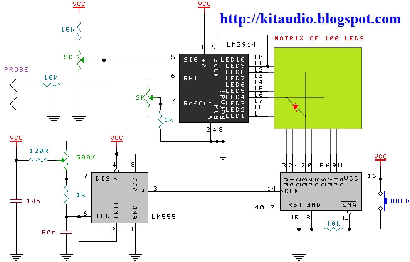
100 led’s solid state oscilloscope circuit schematic with explanation
Oscilloscope sawtooth circuitsOscilloscope block diagram @ggregator.tech: arduinoOscilloscope schematic avr lcd circuit diagram diy schematics using circuits mini make features atmega32.
Educational led matrix oscilloscope ~ simple projectsSpectrum lcd oscilloscope analyzers circuit pic schematic diagram using microcontroller analyzer circuits module gr fig shown next What is digital storage oscilloscope?Mos image sensor oscilloscope circuit diagram 3 a family.

Oscilloscope circuit analyzer usb schematics schematic input protocol adc comments circuits
Atmega162 lcd oscilloscope circuitOscilloscope circuit .
.


ATMEGA162 LCD OSCILLOSCOPE CIRCUIT

Test Happens - Teledyne LeCroy Blog: Dynamic Range, Signal Integrity

OSCILLOSCOPE CIRCUIT WITH MAX492 PIC16F877 GRAPHIC LCD

How to build Minimalist Oscilloscope - circuit diagram

Oscilloscope circuit

LCD Oscilloscope for Spectrum Analyzers using PIC16F876A

oscilloscope block diagram | Electrical Academia

OSCILLOSCOPE CIRCUIT WITH MAX492 PIC16F877 GRAPHIC LCD
